High Impedance Probe
2025
Project GitHub RepositoryWhen I designed my own Geiger counter, I found that I couldn't accurately measure the output voltage of its high voltage supply using a multimeter. This was because the multimeter had an input resistance low enough to appreciably load the high voltage supply. At the ime, I constructed a voltage divider with a 1GΩ resistor in series with the multimeter's input resistance, but I had to accept some voltage dependent error because the input resistance seemed to be non-linear. This remained an ongoing issue as I built more Geiger counters, so I designed a high input resistance active probe.
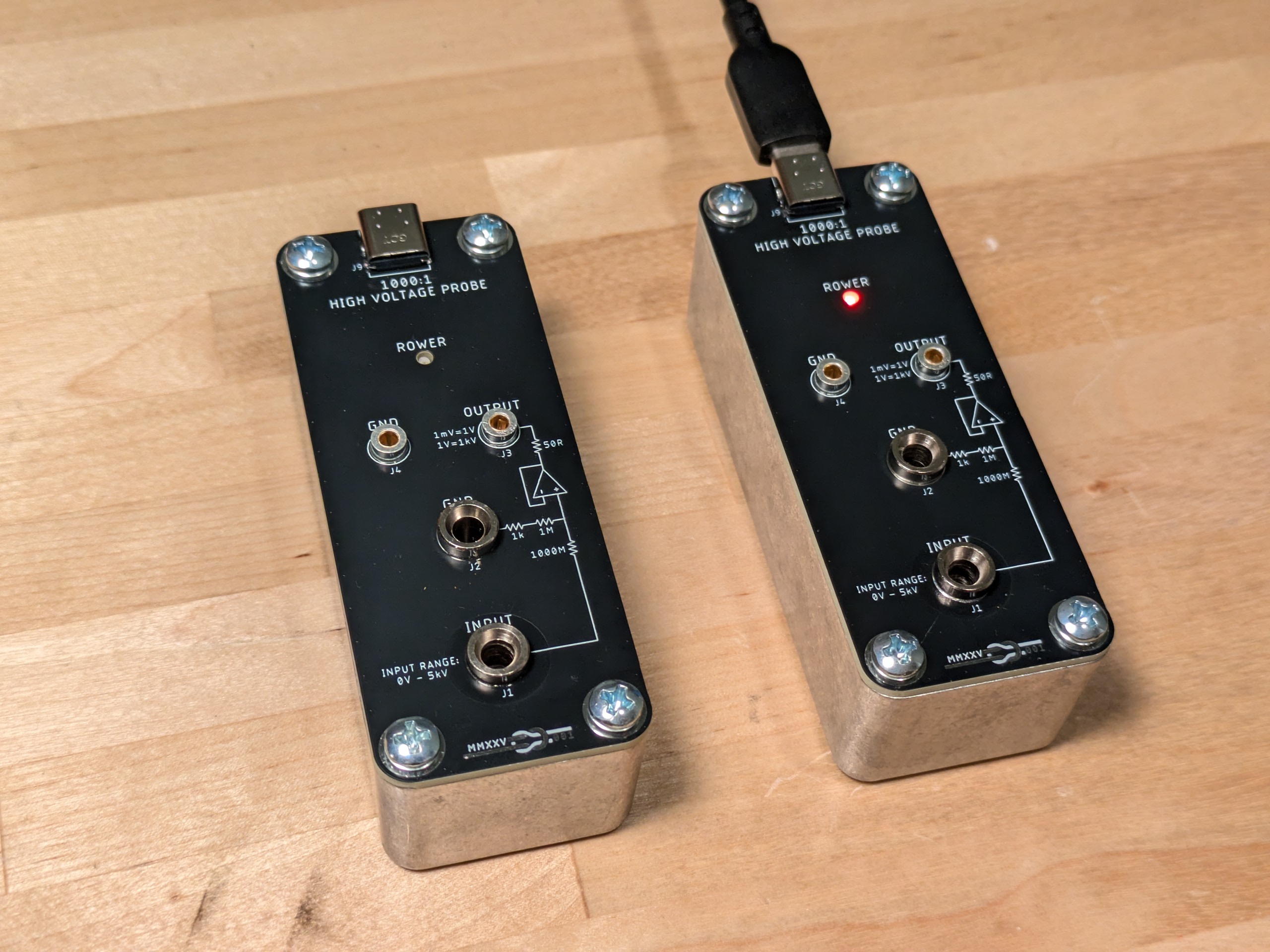
Completed High Impedance Probe
Overview
You will not get an accurate measurement of a low current high voltage supply with a standard multimeter because the nominal 10 MΩ input resistance will load the supply causing it to droop. Oscilloscopes and some multimeters have well defined input resistance which allows external resistors to be used to form accurate voltage dividers. This is effectively what happens in a passive 10:1 oscilloscope probe: The probe has a series resistance of 9 MΩ which forms a 10:1 voltage divider when connected to a 1 MΩ input resistance scope. I say input resistance rather than impedance here because input impedance is a function of frequency. My Siglent SDS 1104X-E oscilloscope has an input capacitance of 15 pF. At 100 MGz, this is \(\frac{1}{2πf\cdot C}=\frac{1}{2π \cdot 100e6 \cdot 15e-12}=106Ω\) which is decidedly less than 1 M Ω. For digital multimeters, the input resistance itself can be poorly controlled. While my 1980's vintage Fluke 8024B that I found in a dumpster measures right on 10 MΩ resistance across its leads when in voltage measurement mode, my modern Fluke 15B+ measures 11 MΩ — it seems they may have used a 10 MΩ resistor rather than a 9 MΩ resistor in the internal voltage divider.
Design
The circuitry of the active probe is very simple: The input is divided down by 1000x with a 1 GΩ resistor followed by 1.001 MΩ and this voltage is buffered by the same op-amp that I used for my picoammeter. The relevant parameters for this application are low input bias current and low input offset voltage. The op-amp sees an effective impedance of 1 MΩ, so a 1 pA input bias current would mean a 1µV offset in the output corresponding to a 1mV measurement error. 150 µV input offset voltage (the max specified value for LMP2231) corresponds to to 150 mV of measurement error. The typical input voltage is only 10µV, so in most cases, the ability of the op-amp to swing to its negative rail and the accuracy of the resistor divider components will define accuracy, not the input offset voltage of the op-amp. The 1 GΩ resistor has a 1% tolerance which is the best you can buy on Digikey.
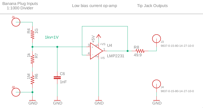
Schematic of Buffer Circuit
TI used standard banana jacks for inputs and tip jacks for the outputs. Tip jacks are sized suck that a standard meter probe can slide into them making it easy to hold the probes in place. Pomona sells probes without the insulation sheath normally seen on meter probes that connect nicely to the banana jacks. The irony of the high voltage side of this circuit having less insulated probes than the low voltage side is not lost on me.
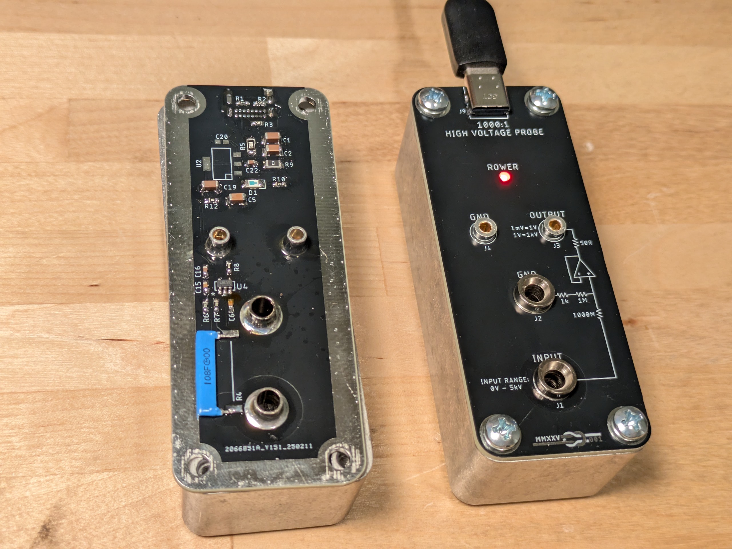
Active Circuitry Inside Box
The circuit is powered over USB with an optional linear regulator that I bypassed on the boards that I hand assembled — I initially thought I would have JLCPCB do the assembly but I decided to assemble by hand since they are simple boards and didn't have the linear regulator on hand. The board is designed around a Hammond 1590BBK box.
Measurements
When my improved Geiger counter is directly measured, the meter registers 231V due to the loading effect of the meter.

Direct Measurement Without High Impedance Probe
With the high impedance probe buffering the measurement, the meter registers 366mV which is 366V. I tested two other identical Geiger counters and say 361V and 364V. The overvoltage protection on these boards is set with a voltage divider into an NPN transistor base, and this voltage corresponds to a base to emitter voltage of around 0.55V showing that this circuit rather than the open loop peak current circuit sets the output voltage in practice.
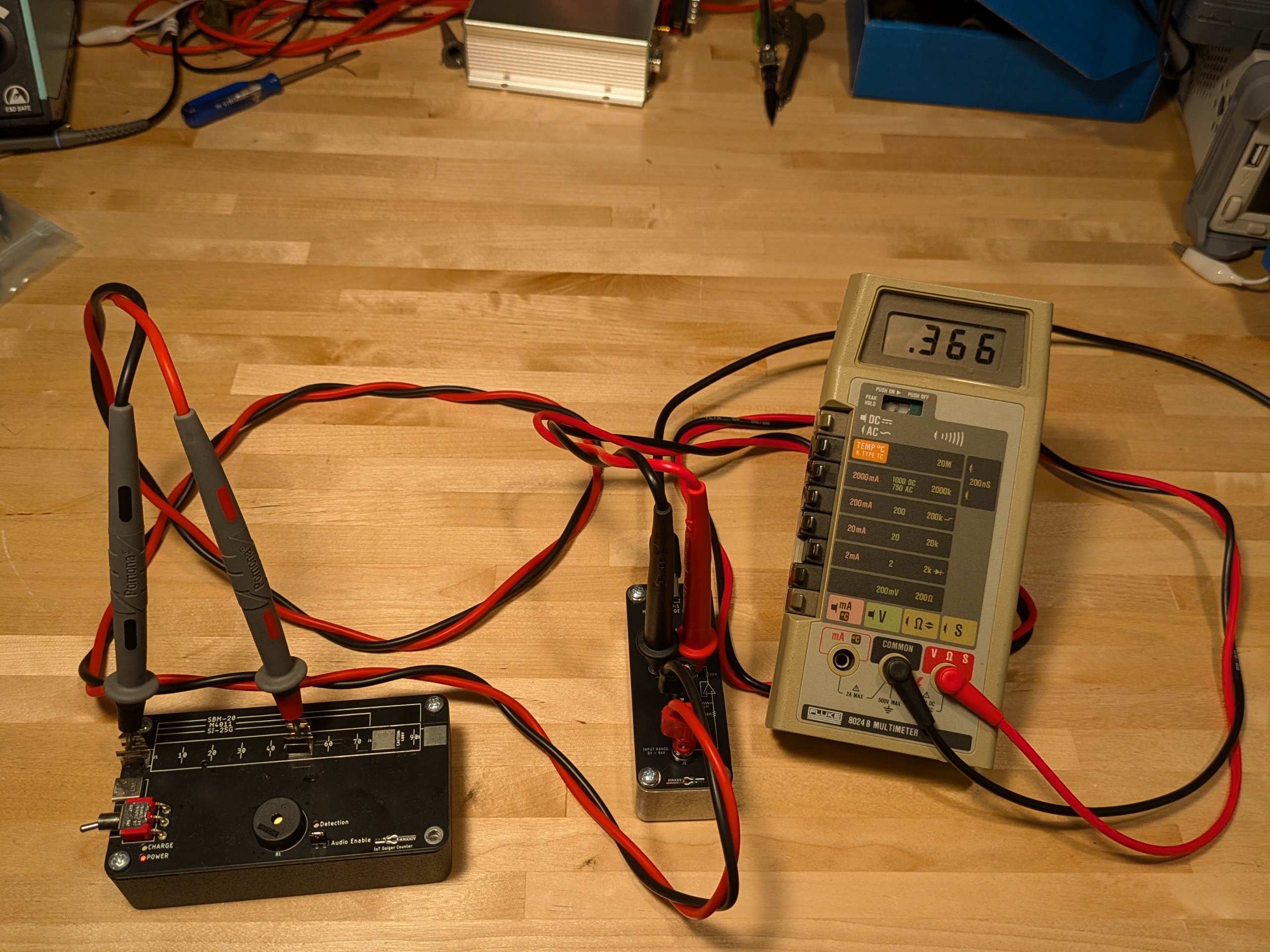
Measurement With High Impedance Probe
Frequency Response
I call this a probe, but it is not going to be a good probe for an oscilloscope. The RC time constant of the input is 1 MΩ multiplied by 1 nF which is 1 ms. The frequency response could be drastically improved if the low side capacitance were removed, but I was more interested in reducing noise than in expanding the frequency response. A well designed wide bandwidth high impedance probe will also include some capacitance in parallel with this high side resistor to keep the capacitive divider ratio of the input of the op-amp and that added capacitor the same as the intentional resistor divider ratio of the two high and low side resistors. Such a probe would also use an op-amp with greater bandwidth than LMP2231.